Texting Dryer
Aug 7th, 2017 - Sep 9th, 2017
My brand new 2017 dryer didn't have a way to disable the loud, obnoxious end-of-cycle buzzer. The goal of this project is to add some hardware to my dryer that will ultimately enable me to get a text when the dryer cycle ends instead of the loud buzzer.
Learning Objectives
Expand knowledge of M2M (machine to machine) protocols
Gain practical experience doing wireless M2M communication
Gain practical experience using the RFM69 transceiver module
Send a text from a cloud service
Power a node from the dryer without requiring extra power source
Create a hub that can accept connections from multiple devices
The Rough Plan - Aug 8, 2017
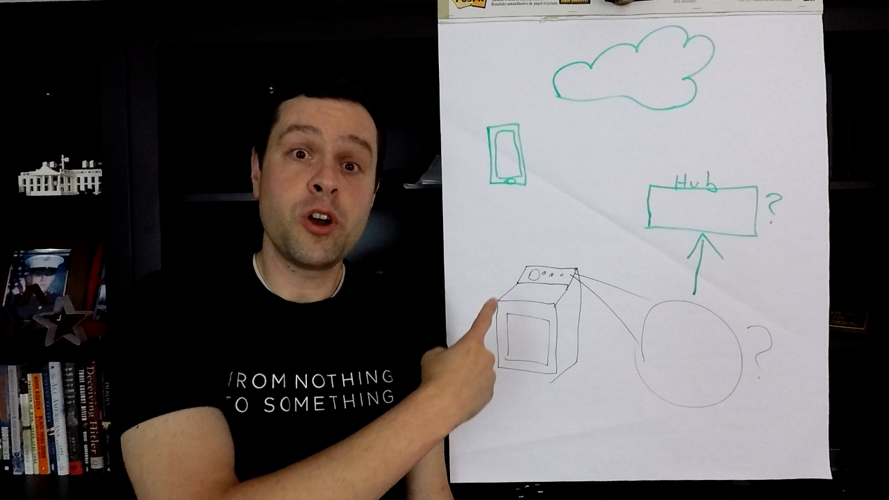
Today I sketched out the rough plan of all the pieces that need to come together to pull this project off. In no particular order they are:
- Hardware device inside dryer
- Hardware device acting as a hub
- Communication link between dryer node and hub
- Communication link between hub and cloud
- Cloud mechanism to send text
I'm going to start with the communication piece between the node and the hub by prototyping a comm link using the RFM69 chip. I also did some research today on protocols that I could use for that comm link. In it's rawest form I could make up my own simple message protocol to send data to the hub but figured I should look into established patterns that might be useful. The ones that caught my eye were MQTT, DDS, and OPC UA. The more standards I can adopt throughout the better so I'm not reinventing the wheel at every turn. Here are some of the good reading links from today.
- Overview of some common protocols
- Extensive list of many protocols across IoT layers
- MQTT and CoAP comparison
RFM69 Prototyping - August 9, 2017
Today I spent the bulk of my time researching the RFM69 module specifically libraries that have already been written to support it on platforms I already have. The idea is to get a working device to device prototype up as quickly as possible. I found that libraries exist for at least the Particle Photon, Arduino, ESP8266 and Raspberry Pi so we should be covered. Apparently the module is more widely used than I was aware when I bought them.
I ran across the MySensors website which has quite a bit of general info on the RFM69 and has written a library for it. The big thing I learned is that the pins on the module are not 5V tolerant so if I want to use an Arduino for either end of the communication channel I'll need to put a level shifter in to get the signals down to 3.3V. I have level shifters but that's just extra complexity and hardware I don't need. At this point I'm going to try to prototype the comm link with two Photons since they are 3.3V.
The other big discovery of the day came inside the dryer. I tore the back off to get some more insight into the end-of-cycle buzzer. I was hoping it would be 12V but alas it's actually a 120V buzzer. It signals for 5 seconds and then shuts off. So the next question becomes, can I steal 120V for 5 seconds and get an RFM69 message out. I'll tackle that problem after I get the comm link prototyped. The positive that came out of the dryer was that it had a schematic taped inside the back so that was pretty cool.


Soldering and the Adafruit Trinket - August 12, 2017
I decided that I want to use a Raspberry Pi as the hub so instead of prototyping with two Photons I'm going to use a Pi as one end of the RFM69 comm link. I also got my Adafruit Trinkets which is what I'm hoping to use in the dryer so I'm going to prototype the comm link with that and the Pi. To get things ready I did some soldering. Well, more accurately, my 10 year old daughter did some soldering. She's shown some interest in programming and tinkering so I decided this would be a good first project soldering some leads to the RFM69 and the headers to the Trinket. She did a great job.
One of the things I learned about the RFM module is that you should NOT run it without an antenna even for close range prototyping. For the 433MHz modules that I have the antenna needs to be approximately 165mm. Instead of having that long of a wire hanging off the modules I decided to try to DIY the antenna style I see that you can buy online. To do that I took the wire, cut to length, and wrapped it around a screwdriver shaft a few times. We'll see how they work.
Since I found that the buzzer operates at 120VAC we need a way to turn 5 seconds of line voltage to 3.3VDC to power our circuit in the dryer long enough to send a message to the hub. For that I've ordered two power supplies to test with. I think either one of them should do the trick but got one of each just in case.
Trinket and Power Problems - August 14, 2017
Today was full of problems. I started on trying to get a simple comm link up between the two RFM69 modules using a Pi and Trinket. Adafruit has instructions for setting up the Trinket but I kept getting a compiler error in the Arduino IDE. It was telling me it couldn't read the avrdude.conf file that I replaced per the instructions on Adafruit. After about an hour of messing with it I found that the Adafruit .conf file is out of data and the fix appears to have been just updating the Arduino AVR Boards package in Boards Manager. After getting passed that hurdle I'm still getting the following error.
avrdude: Error: Could not find USBtiny device (0x1781/0xc9f)
This appears to be due to the fact that the Trinket doesn't like USB 3.0 ports so Adafruit recommends a 2.0 hub. Ugh! I don't have one of those so I'll have to go grab one.
The other problem I ran into today is that my RFM69 modules are the high power version. This is good for getting the signal through walls and to my hub but bad in that it requires so much power (up to 1 AMP according so some sites!). At that power level I can't use the 3.3V source on the Pi for power nor can I share the Trinket's supply on my node. Once my AC/DC converter arrives for the node it will have plenty of juice to supply both the trinket and the RFM module. Until then I'm going to try using an old power supply I built for another project to provide power to the node and a separate supply and 3.3V regulator on the Pi side. Ultimately I think I'll want the non-high-powered version on the Pi end since it's just a receiver and then I won't need any special power handling on that end.

Old 3.3V power supply I made for a project years ago.

Trinket Bootloader Working - August 16, 2017
I picked up an ONN USB 2.0 4 port hub today from Walmart to see if that would solve the issue of the Arduino IDE not recognizing the Trinket. Plugged it in and it immediately went into bootloader mode with the pulsing red LED. 🕺🕺🕺🕺After that I loaded the flashing LED test firmware and confirmed that it worked as well. On startup the Trinket will go into bootloader mode for 10 seconds waiting for updated firmware. If no firmware update comes through in that time then it will start to run the code already flashed to it. Anytime you need get back into bootloader mode you just push the button. I hate that it requires the 2.0 port being that it's 2017 but my impression overall of the Trinket from plowing through the docs and trying to get the IDE working is that it's not really actively supported anymore. I definitely would not recommend it as a starting point for a total beginner.
More Trinket Problems 😡😡😡 - August 17, 2017
Well the Trinket woes continue. When the Adafruit marketing page says "Hardware I2C / SPI capability for breakout & sensor interfacing" they mean "Roll-your-own SPI capability" because the built-in Arduino SPI does not work. You have to know how to manually handle the hardware registers to accomplish hardware SPI. This is confirmed in their forum. It's not the end of the world but would be nice if it were called out under the section that talks about the other non-Arduino compatible things about the Trinket. What they point you to is the raw register implementation of SPI they wrote for another project.
The other Trinket roadblock I hit today was the 5K flash limitation. The ATtiny85 has 8K of flash but the the bootloader takes almost 3K. I was trying to shortcut the comm link implementation my using the MySensors library on the Trinket and Raspberry Pi. I got the Pi end up and running (compiling and running without errors) but even the most trivial example on the Arduino requires at least 7K. It took me close to 3 hours to even get the MySensors library building for the Trinket because the library doesn't properly isolate pieces of the implementation. For example, even after specifying MY_SOFTSPI which is supposed to tell the library to use software SPI I was still getting hardware SPI compiler errors. Long story short, I spent 3 hours finding out that the MySensors library was too big for the Trinket. Sooooooo...we're going to have to go with a different RFM69 lib for the Trinket AND supply our own hardware SPI implementation based on the Adafruit code.
I could always just switch the platform to an ESP8266, Photon, or even an Arduino UNO but those are overkill for the dryer node. I'm convinced the Trinket (specifically the ATtiny85) is a good fit for the project. It's just gonna take a little effort to get there.


🔥 🔥 🔥 🔥 🔥 🔥
COMM LINK SUCCESS!!! - August 18, 2017
Was up until 1AM last night attaching the logic analyzer to both the Trinket and the Pi trying to figure out why the link wasn't working despite having compiled code running on both ends that "appeared" not to have any errors. Well, the first problem was the SPI bus labeling on the Trinket. When using SPI you will see the common terms MOSI and MISO. They stand for Master Out Slave In (MOSI) and Master In Slave Out (MISO). Communication direction in SPI is always referred to from the perspective of the master. So, as a slave device you may have a pin labeled MOSI which is not your output as a slave. It's the input. The confusion happens when the line of what's considered a slave or master gets blurry. Things like sensors are obviously slave devices. They have no ability to operate as master on the bus. The Trinket, however, is perfectly capable of working as master and driving the clock line for connected slave devices (aka the RFM69). Despite that fact the nice, pretty diagram labels MISO and MOSI on the Trinket as if it were a slave device. In other words, backward from how we are using it. The logic analyzer quickly helped me find this because I saw the output data showing up on what I was calling the Master In Slave Out line (or input to the Trinket) when I really wanted it showing up on the MOSI line. The TLDR; version of that is we have to connect the Trinket MISO to the RFM MOSI and the Trinket MOSI to the RFM MISO which is uncommon for many projects you will encounter. It's just what happens when both devices consider themselves slave nodes.
With that problem solved I spent the next several hours verifying all of the bus signals with the logic analyzer to ensure everything looked good...and it did. Still, I was getting nothing between the nodes. At this point I was using the NodeJS RFM library on the Pi. I decided that maybe it was the problem so I switched to a C++ version I found. That wasn't working either. The best I would get was an occasional garbage packet. That should have been my clue to the problem but alas it was very late and I wasn't thinking right. I woke up this morning and the solution came to me as clear as the new day. GROUND!!!! I just made a video on breadboards not two weeks ago explaining how they work and one of the important gotchas: the power rails on long breadboards don't connect the entire length. I wasn't grounding the RFM69 module properly because I had it connected to a ground rail on the breadboard that wasn't actually grounded! Move the pin 4 terminals over to the grounded side of the rail and MAGIC...it started working immediately. We now have a working prototype of the RFM comm link between a Raspberry Pi and Trinket!
AC/DC Converters and Plan Update - August 22, 2017
Got the AC to DC converters in which is really exciting so we'll have something to power the node in the dryer. Here are the two converters I purchased.
At this point I think I'll go with the IRM05 as it's fully enclosed and I won't have to worry about dust or bugs finding their way into the high voltage components.
I've also decided that we'll be using MQTT as the protocol from hub to cloud. For the cloud piece I'm going to use Losant as I've been gaining some experience with that recently and really like how easy it is. As a bonus it accepts MQTT messages out of the box.

RFM69 Pull Request and Lost Antennae - August 25, 2017
In an effort to get the Trinket code all squared away I remembered that I made a few changes to the RFM library to make everything work since it didn't support the ATtiny85 out of the box. I could just take my modified version of the code and be on my way but part of using open source software is contributing back. If you fork a project and build upon it in such a way that could benefit others then it's good OSS (open source software) etiquette to try to give those changes back to the community. In my scenario I needed to add support to the RFM69 library to support ATtiny microcontrollers. I think that could be useful to other members of the community using the RFM modules so instead of just hacking together some working code I cleaned it all up and submitted the changes back to LowPowerLab as a pull request. Now, it may or may not be accepted and merged but I feel like I've done my duty. At this point the code for the dryer node is all but finished.
In an attempt to improve my RFM69 range I ordered some 433MHz antennae. Instead of waiting for weeks to get them from China I hacked a shortcut by ordering two Si4432 transceiver modules from a US source that includes the spring antenna. The problem occurred when I got the email from ebay saying my package was delivered....to my old address in Washington. Ugh! So now I have to wait for the people who bought our house to ship them down to me.
I also took some time today to play with the MQTT broker in Losant to see if it will suite our needs for processing messages from the gateway. More to come on that soon.
End-To-End Working - August 31, 2017
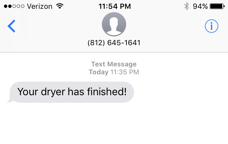
Today was awesome. I finally got the complete end-to-end test of the project working. I used the RS15-3.3 to convert AC line voltage down to 3.3V as an authentic test of what the buzzer signal would look like. I also went through and setup the Losant integration from scratch to allow the Pi gateway to connect and forward messages from nodes up to the Losant MQTT broker. When using Losant always remember to deploy your workflow or you'll be pounding your head as to why things aren't working. For the gateway piece I finally settled on using Python since the NodeJS RFM69 module was flaky and I didn't want to spend time debugging it. The python port seems to work just fine so I went with that. It requires py-spidev and RPi.GPIO so I also had to set those up. The only other piece I needed for the gateway was an MQTT module. Losant has a python implementation but it's for devices connecting directly to the service to update state which isn't exactly what I'm doing. I want to be able to send messages to arbitrary MQTT topics so I went with paho-mqtt. Because the Losant MQTT broker requires authentication you have to configure a security access key in your Losant application and use the key as the username and the secret as the password. Once that's all setup it's just a matter of creating a simple workflow in Losant to trigger an SMS text based on the MQTT message. With everything running all I have to do is flip the power on to my AC/DC converter and I get a text telling me my dryer is finished!


Code is Ready...and Docker is Awesome - September 1, 2017
With the end-to-end demo working the project is basically at a point that I can install it into my dryer for a real world test but I wanted to stop and take some time to make the code shareable so others could recreate the project. The Trinket code is simple enough so I just stuck it in a Github repo and anybody can pull it down and use it. The Pi is a bit trickier. For the Python code to run I had to install a bunch of packages, pip install paho-mqtt and make sure the right privileges are used to run it. Since the Pi runs an entire operating system there are lots of things that could prevent our gateway code from running out of the box. To help alleviate that and make it as easy as possible for people to use the code I considered created a custom Raspbian image that had all of the necessary packages installed so all you would need to do is pull down the source code and run it. It turns out that rolling your own image can be tricky. Yes, you can just configure an image and then rip it off the SD card but then it has the unique fingerprint from my install of the OS that I'd be passing around. While not the worst we could do I didn't like that idea. Building an image from scratch seemed...complicated from the things I read. Docker to the rescue.
Before today I had only a passing knowledge of Docker and what it's purpose is. After today it's one of my new favorite toys. The idea in Docker is that you run containers based on images. Everything inside the container can be thought of as something of a virtual machine where you can control the environment. Turns out it's supported on the Raspberry Pi. After many hours of Googling and learning I was able to figure out how to create a base image for Python dev on the Pi as well as an additional image based on the first that executes the gateway code for my project. All of this independent of the environment running on the end-user's Pi. All they need to configure is internet access and ensure that SPI access is enabled via raspi-config. After that, the image I created takes care of everything else including running the code. It's almost magical. Having spent hours trying to reproduce somebody else's project on a Pi and getting mired down in configuration issues this approach amazed me. It worked perfectly the first time. My Docker container received the RFM69 message, forwarded it to Losant and I got a text. Perfect. I still need to put together README files for both repositories but they are available as well as the Docker image with the gateway code in it.
Commands to install Docker on the Pi.
Texting Dryer Sends a Text - September 9, 2017
Today I did a full, end to end test in the dryer using the IRM 05 to power the Trinket. I hooked everything up inside and was able to see the dryer send a text using nothing by the end-of-cycle buzzer power. At this point I would normally call the project finished but after reaching out on Twitter a couple of weeks ago looking for someone to collaborate on the project there is more coming. The awesome folks at Agility Design have offered to collaborate and create a PCB and enclosure for use to take the project to the next level. While we're going to start in on the next project (stay tuned to the blog for more) I will continue to post updates here as the PCB and enclosure pieces come together. Really exciting stuff.
Printed Circuit Board (PCB)
I got a batch of PCBs from Agility Design. They look amazing and worked first try. They even sent me a couple that were fully populated. Now that I've confirmed the design I've updated the Github repo with the files necessary to create the board if you are interested in recreating the project or using it as a base for your own project.


3D Printed Case
I took the 3D case design from Agility Design and sent it off to Fictiv to be printed since I don't own a 3D printer...yet. If you've never heard of Fictiv they offer 3D printing and CNC services for your project designs. I had a chance to meet this team when I was in San Francisco a while back and they are a great group of people and you should definitely check them out. When I got the case parts back in they were a perfect fit with the PCB first try. With that the only thing left is to install the project permanently in my dryer.
Trinket Lessons Learned
- It does NOT play nicely with the USB ports on a Macbook. USB 2.0 hub required
- Hardware SPI not supported out of the box in Arduino IDE
- Not all IO pins are created equal. Specifically watch out for GPIO #3 which has a pullup resistor to 3.3V which makes it not suitable for input
- Because of the USB sharing on pins #3 and #4 if you use those pins you have to remove the Trinket from the circuit to flash it
- 8K of total flash but only about 5K after the bootloader
- It considers itself a slave so MOSI and MISO are labelled as such. If you want to use it as a master this is VERY important.